



Catheter Flow Rate Tester: Operating Principle, Applicable Standards and Test Parameters
2026-10-08 16:56Catheter Flow Rate Tester: Operating Principle, Applicable Standards and Test Parameters
What the Instrument Is Designed to Measure
A catheter flow rate tester is a laboratory instrument that quantifies how much fluid a catheter can deliver under a defined driving condition. The measured quantity is volume or mass of water passing through the catheter within a specified time, expressed as millilitres per minute. Flow rate is a functional property rather than a dimensional one: it is not derived from the inner diameter by calculation, but obtained by letting water actually run through the finished assembly.
1.1 Flow rate as a released performance characteristic
During catheter use, the clinical outcome depends partly on whether the device delivers fluid at the rate intended by its design. A lumen that is narrower than specified, a connector whose bore was reduced during moulding, or a residual membrane partially covering a side eye will all reduce throughput. None of these are reliably caught by dimensional inspection alone. Flow measurement therefore functions as a cumulative verification of the entire fluid path — tube, taper, shoulder, connector, filter and any side aperture in one reading.
1.2 Why nominally identical catheters differ
Influence on flow is distributed across many features: internal diameter and its tolerance, catheter length, wall smoothness, the hydrophilic or oleophobic character of the material surface, the through-bore geometry of the proximal fitting, and moulding flash left inside the lumen. Two samples of the same nominal size can pass dimensional checks and still diverge measurably in delivered flow. This is why flow is specified as a test method with fixed boundary conditions rather than as an open-ended measurement.
Operating Principle and Instrument Architecture
2.1 The gravity-feed hydrostatic head method
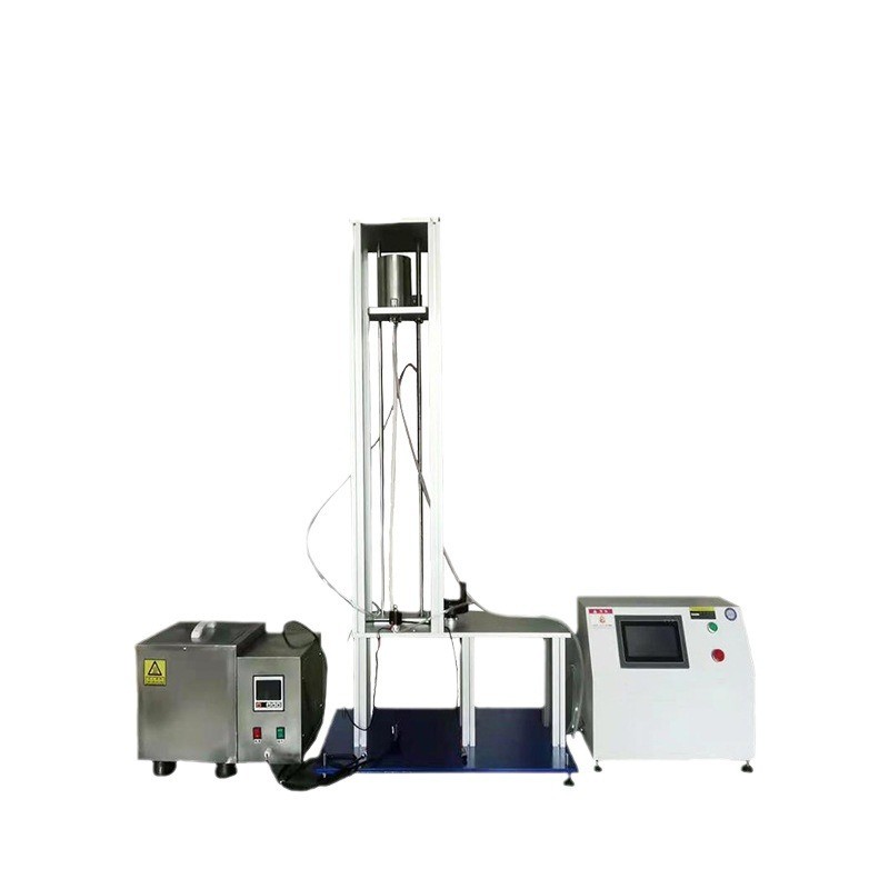
The prevailing method places the catheter upstream of a constant-level water reservoir and drives flow by hydrostatic pressure. The test specification fixes the vertical distance between the water surface and the catheter outlet. In the configuration described here, the static water level height is set to 1000 ± 5 mm, which corresponds to a hydrostatic head of approximately 9.8 kPa. A water pump with automatic circulation continuously refills the reservoir so that the liquid surface does not fall during the measurement window; a fine regulating valve trims the inflow rate, and an overflow path maintains the level.
Holding the head constant is the essential engineering requirement of this method. If the reservoir level drifts, the driving pressure drifts with it, and the flow value no longer corresponds to the specified condition. Over-pressure filling, rather than a closed-loop pump, is the conventional way to guarantee stability, because the overflow simply discharges whatever is not drawn through the catheter.
2.2 Driving mechanism, fixtures and data acquisition
The catheter is mounted on a drive mechanism that is connected to the measuring device, and the instrument records the applied pressure value, the holding time and the resulting flow rate automatically. Two consequences follow from this architecture. First, the operator does not read a scale or start a stopwatch manually, so reaction delay and parallax error are removed from the result. Second, the fixture defines what the instrument can be used for: a fixture set that accommodates multiple catheter types and includes a standard conical (luer-type) connection allows the same bench to serve urinary, drainage, infusion and airway devices without rework of the test rig.
Control is provided through an industrial capacitive touchscreen with a menu-driven interface. Parameters such as head height, test duration and sample identification are entered on the panel, and a built-in micro printer produces a hard copy of the result at the end of the run.
Catheter Types Covered
3.1 As a non-intravascular catheter tester
A non-intravascular catheter tester is specified by its ability to hold these geometries — different outer diameters, taper types and wall materials — without leaking at the connection, since a leak at the fitting reads as reduced flow in the lumen.
3.2 As a urinary catheter flow tester
Urinary catheters are the most common reason this instrument is purchased, because the flow requirement in the urethral-catheter product standard is explicit and routinely checked during registration testing and batch release. A urinary catheter flow tester is used at the production stage for lot verification, by contract manufacturers for incoming-quality checks on outsourced tubing, and by third-party laboratories performing registration-type testing.
3.3 As an intravascular flow test bench
The same principle extends to intravascular devices under ISO 10555-1 — peripheral and central venous catheters, dialysis catheters, introducing and guide catheters. The difference lies in the specified head, conditioning temperature and acceptance limits, not in the architecture of the rig. Devices intended for power injection require a separate, higher-pressure method and are not served by a gravity-feed bench.
Key Technical Parameters
4.1 Hydrostatic head and circulation
Static water level height of 1000 ± 5 mm, maintained by an automatically circulating pump. The tolerance band of ±5 mm is set so that variation in driving pressure remains negligible relative to the head itself.
4.2 Capacity, timing and measurement
Flow velocity greater than 500 ml/min. This is a property of the reservoir and supply path: it must be able to deliver more than the catheter under test will pass, so that the level remains constant under the maximum expected load. Time control from 0 to 60 minutes, accuracy ±1 second. Flow calculated by graduated-cylinder method.
4.3 Physical envelope
Overall dimensions of 400 × 290 × 1100 mm and a net weight of 40 kg. The tall, narrow profile is dictated by the 1000 mm head: the reservoir must sit more than a metre above the outlet, which makes this a bench-standing unit rather than a true desktop instrument. Mains supply is 220 V, 50 Hz.
Typical Operating Sequence
5.1 Preparation
The catheter is conditioned as the applicable annex requires. The reservoir is filled, the level set and verified against the scale, and the pump circulated until the surface is stable. If thermal conditioning is used, the bath is brought to temperature and allowed to stabilise. The appropriate fixture is fitted to the constant-level vessel's taper connection and checked for leak-free seating.
5.2 Running the test and recording the result
The catheter is mounted in the fixture with the specified hanging length and its outlet positioned below the reservoir. Test duration is set on the touchscreen, the clamp or valve opening the flow path is actuated, and effluent is collected in the measure. The instrument records pressure, holding time and calculated flow, and the micro printer produces a copy carrying the sample identification. Repeating the run on the same specimen characterises repeatability, which manual collection cannot do consistently.
Role Within Quality Control
Flow test benches of this type are catheter flow testing equipment used at three points: during development, where a change in tubing supplier, wall thickness or connector moulding is evaluated against delivered flow; at batch release, where a sampling plan checks production lots against the product specification; and in failure analysis, where a complaint is investigated by measuring retained samples from the same lot. It also appears in external test laboratories and in procurement inspection by hospitals and government supply agencies evaluating tendered devices.
Selection Considerations
7.1 Standard coverage
Because several methods share one architecture, the practical differentiator is whether one bench satisfies multiple annexes at once, and whether the stated head, fixture and collection method match each of them. An instrument whose declared compliance spans a general method standard together with the specific product standards relevant to a manufacturer's own catalogue reduces the number of benches required.
7.2 Fixture range and method flexibility
Fixture interchangeability determines real-world coverage more than the control panel does. Equally, a bench that can switch between volumetric collection and gravimetric collection — or accept an inline flowmeter in place of the cylinder — can serve both high-flow drainage devices and low-flow micro-lumen catheters, where a single collection method reaches its resolution limit.